
You are here : Home | Water Storage Tanks | Library | WRAS Cold Water Storage Cisterns
WRAS Cold Water Storage Cisterns
Introduction
The installation and use of cold water storage cisterns and sectional tanks connected to the public water supply must comply with the Water Supply (Water Fittings) Regulations 1999 in England and Wales and the technically identical Bye laws 2000 in Scotland. Reference in this document to Regulations covers the requirements of both sets of legislation. Similar regulations are planned for Northern Ireland. It is a legal obligation that the Water Supplier must be notified in advance of most installation work on water systems (Regulation 5). One of the purposes of the Regulations is to prevent contamination of water and a major risk of contamination is by back flow – the flow of water in a direction opposite to that intended. The level of back flow protection is determined by an assessment of the contamination risk posed by either the fluid in the cistern or the fluid or process downstream of the cistern.
Regulation 3 requires all water fittings to be installed, connected, maintained or disconnected in a manner which complies with the Regulations and Regulation 4 requires this work to be carried out in a workmanlike manner.
This Information and Guidance Note has been produced by the Water Supply Industry in conjunction with the Association of Tank and Cistern Manufacturers (ATCM), whose help is gratefully acknowledged. The document has been endorsed by the UK Water Suppliers and following its recommendations for the design and installation of mains supplies to cisterns and sectional tanks should ensure that the appropriate back flow protection is provided, commensurate with the risk related to the fluid category of the contents or downstream process, to comply with the Regulations.
Scope
For the purposes of this document all references to cisterns will encompass all one-piece cisterns, sectional tanks or any other receiving vessel open to atmospheric pressure.
The risk of contamination by back flow from the use of cisterns can occur in both domestic and non-domestic premises. This Note will be of use to those who undertake the design and installation of water services and their fittings and for those who are responsible for the enforcement of the Regulations.
General Requirements
The complete installation shall comply with the requirements of the Water Supply (Water Fittings) Regulations 1999.
Inlets to all cisterns should be provided with a servicing valve to facilitate maintenance.
The float operated valve or equivalent shall be securely and rigidly attached to the cistern and shall be adjustable so that the valve closes when the level of water is not less than 25mm below the overflowing level of the cistern.
Except for cisterns supplying water to primary circuits or heating circuits, all outlets other than vent pipes, overflow pipes, and warning pipes relating to storage cisterns supplying water to cold water taps and secondary hot water systems, should be fitted with a servicing valve as close to the cistern as is reasonably practicable.
Details of fittings approved for their compliance with the Regulations’ requirements can be found in the ‘Water Fittings and Materials Directory’. Copies of the Directory are available from the Water Regulations Advisory Scheme.
Definitions
‘Air gap’ means a visible, unobstructed and complete physical air break between the lowest level of water discharge and the level of potentially contaminated fluid downstream (critical water level) within a cistern that:
a) Is not less than 20mm or twice the internal diameter of the inlet pipe whichever is the greater; and
b) From which water discharges at not more than 15° from the vertical centreline of the water stream.
‘Dimension D’ means the maximum internal diameter within the last metre of the supply pipe or the DN of the inlet connection.
‘Critical level’ means the physical or piezometric level of the fluid in any part of the cistern a minimum of two seconds after closing the water inlet, starting from maximum water level. (For AA Air gaps the critical water level can be assumed to be the Spillover level).
‘Invert’ refers to the lowest point of a horizontal pipe.
‘Maximum level’ means the highest physical or piezometric level of the fluid reached in any part of the cistern when operated continuously under fault conditions.
‘Soffit’ refers to the highest point of a horizontal pipe.
‘Spillover level’ means the level at which the fluid in a cistern will first spill over the top edge of the cistern if the inflow of water exceeds the outflow through any outlet and any overflow pipe.
‘Type AA – Air gap with unrestricted discharge’
(Fluid 5) means a non-mechanical back flow prevention arrangement of water fittings where water is discharged through an air gap into a cistern which has at all times an unrestricted spillover to the atmosphere. The air gap is measured vertically downwards from the lowest point of the inlet discharge orifice to the spillover level.
‘Type AB – Air gap with weir overflow’ (Fluid 5) means a non-mechanical back flow prevention arrangement of water fittings complying with Type AA, except that the air gap is the vertical distance from the lowest point of the discharge orifice which discharges into the cistern, to the critical water level of the rectangular weir overflow.
‘Type AC – Air gap with vented submerged inlet and circular overflow’ (Fluid 3) means a non-mechanical back flow prevention arrangement of water fittings with a vented, but submerged, inlet; the air gap being measured vertically downwards from the lowest point of the air inlet to the critical level.
‘Type AD – Air gap with injector’ (Fluid 5) means a non-mechanical back flow prevention arrangement of water fittings with a horizontal injector and a physical air gap of 20mm or twice the inlet diameter, whichever is the greater.
‘Type AF – Air gap with circular overflow’ (Fluid 4) means a non-mechanical back flow prevention arrangement of water fittings with an air gap measured downwards from the lowest point of the discharge orifice, which discharges into the cistern, to the critical level. For size of overflow see Section 9.
‘Type AG – Air gap arrangement with minimum size circular overflow’ (Fluid 3) means a non-mechanical back flow prevention arrangement of water fittings with an air gap measured downwards from the lowest point of the discharge orifice, which discharges into the cistern, to the critical level. For size of overflow see Section 9.
‘Overflow pipe’ means a pipe from a cistern in which water flows only when the water level in the cistern exceeds a predetermined level.
‘Warning Pipe’ means an overflow pipe with its inlet located in the cistern at such a height that it will start to flow before the main overflow operates and with its outlet located in a position where the discharge of water can be readily seen.
Notification Requirements
In most cases, before work starts on any proposed installation, the Water Supplier’s consent must be obtained by prior notification of the details of the proposed work. Installing or using fittings without the required consent could result in a criminal prosecution (Regulation 5). The details to be notified are given in Regulation 5. Contact details for Water Suppliers are available on the WRAS website www.wras.co.uk.
Fluid Categories and Examples
FLUID CATEGORY 1
Wholesome water supplied by a water undertaker.
Example: Water supplied directly from the supply pipe.
FLUID CATEGORY 2
Water which would be in fluid category 1 but for its aesthetic quality being impaired owing to a change in temperature, change in taste, odour or appearance.
Example: Hot water supplies.
FLUID CATEGORY 3
Fluid which represents a slight health hazard because of the concentration of substances of low toxicity, including any fluid that contains:
Ethylene glycol, copper sulphate or similar chemical additives, or sodium hypochlorite (chloros and common disinfectants).
Example: Water in primary circuits and heating systems (with or without additives) in domestic premises.
FLUID CATEGORY 4
Fluid which represents a significant health hazard due to the concentration of toxic substances, including any fluid that contains:
Chemical, carcinogenic substances or pesticides or environmental organisms of potential health significance.
Example: Commercial clothes washing machines (excluding those used for laundry contaminated with animal or human fluids or waste).
FLUID CATEGORY 5
Fluid representing a serious health hazard because of the concentration of pathogenic organisms, radioactive or very toxic substances including fluid which contains faecal material or other human waste, butchery or other animal waste or pathogens from any other source.
Examples: grey water recycling cisterns, medical equipment with submerged inlets, a cistern which also receives recycled process water, a hose union tap used in an abattoir or mortuary.
Greater detail on back flow risk fluid categories and of back flow prevention devices is available in Section 6 of the WRAS Water Regulations Guide.
Evaluation of Back flow Requirements
Before an installation can commence the requirements to prevent back flow need to be determined. The following guide can be used to determine the back flow requirements. The fluid category determined will need to be verified with the Water Supplier during notification (see Section 5).
a) The fluid category of the contents or the downstream fluid/process is determined. Some helpful information is available on the WRAS website regarding fluid categories for some chemicals, equipment etc.
b) Identify the appropriate air gaps or back flow devices that can safeguard against the given fluid category.
c) Select the appropriate air gap or back flow device that bests suites the application.
d) Select the appropriate inlet device/float valve and the appropriate cistern (see Section 8).
8. Acceptable Cisterns and Inlet Devices
8.1 Fluid Category 1 or 2 Applications
The WRAS Water Fittings and Materials Directory lists products that have been shown to comply with the requirements of the Regulators’ Performance Specifications. Products can be found listed in their respective Directory Sections as follows:
a) Cisterns Section 0120 and also, when modified and installed compliant to Water Regulations Schedule 2:16, Section 0130, 0135, 0140 and 0170.
Inlet Devices Sections 2080, 2090, 2100, 2105, 2120, 2125, 2150 and 2154 (level control valves)
8.2 Fluid Category 3, 4 or 5 Applications
a) Cisterns Sections 0130, 0135, 0140, 0170, 0220, 0225 and 0230.
Inlet Devices Sections 2080, 2090, 2100, 2105, 2120, 2125, 2150 and 2154 (level control valves)
b) Cisterns compliant to BS EN 13280 (formerly BS 7491), BS 1564 Type 1 and BS 4213.
Note: Installation of the components must be such that the complete assembly complies with the Regulators’ Specification for back flow prevention arrangements and devices.
Jointing and sealing compounds must comply with BS6920 and suitable ones are listed in the WRAS Water Fittings and Materials Directory.
Design Parameters
The overflow pipe, inclusive of insect or vermin screen if fitted, shall be capable of draining the maximum inlet flow without compromising the inlet air gap.
The overflow/warning pipe arrangement must include an air break prior to a connection to a drain.
The overflow/warning pipe before the air break to drain must not be of such a length that it will restrict the flow, causing the air gap to be compromised.
For the type AG air gap the overflow/warning pipe bore diameter shall not be less than 19mm. For practical reasons the overflow diameter should be twice that of the inlet bore diameter.
For the type AF air gap the overflow/warning pipe minimum cross sectional area throughout its length shall be not less than four times the inlet pipe cross sectional area.
Given the practical difficulty of determining on site the ‘Critical Water Level’ within a cistern, it is permissible to take the ‘Maximum Level’ as the equivalent defining level when determining the relative positioning of a mains inlet or float valve. The soffit (top) of the overflow can be considered to be the ‘Maximum Level’ for AF and AG Air gaps only.
For the type AA air gap, the critical water level can be assumed to be the spillover level around the top of the cistern.
For the type AB air gap the critical water level can either be determined by test (see the Regulators Specification for back flow prevention arrangements and devices and prEN 13077: ‘Devices to prevent pollution by back flow of potable water – Air gap with non-circular overflow (unrestricted) – Family A-Type B’), or the critical level above the spillover level of the weir (h) can be read from the log graph in Appendix A, for single inlet supplies and supplies having a velocity of not more than 3m/s only.
Type AC (with vented submerged inlet) and type AD (with injector) air gaps are not covered in this document.
The warning pipe invert is to be located a minimum of 25mm above the maximum working level of the cistern.
The minimum air gap must not be less than 20mm or twice the internal diameter of the inlet pipe, whichever is the greater.
a) Cisterns of actual capacity less than 1000 L
A warning pipe is required.
b) Cisterns of actual capacity 1000 L to 5000 L
An overflow and warning pipe are required. The minimum recommended size of the warning pipe is 25mm bore diameter.
c) Cisterns of actual capacity greater than 5000 L
An overflow and warning pipe are required. The minimum recommended size of the warning pipe is 25mm bore diameter.
For cisterns greater than 1000 litres the invert of the overflow shall be not less than 50 mm above the maximum working level of the cistern.
Alternatively, the warning pipe may be omitted provided an equally effective alternative warning device is fitted e.g. a suitable audible or visual alarm.
Note: Reference to the ‘actual capacity’ of a cistern refers to the maximum volume which it could hold when filled to its overflowing level.
Cistern Inlet Design for Fluid Category 1 & 2
When an installation is intended to provide wholesome water it must comply with Clause G16.13 of the Government Guidance viz.:
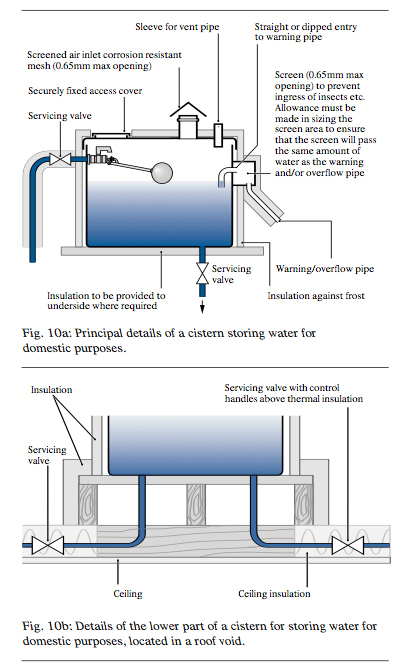
Cisterns storing water for domestic purposes should be watertight and, where required, be lined or coated with a suitable impermeable material; they shall be provided with warning and overflow connections, as appropriate, which are so constructed and arranged as to exclude insects. They should have a rigid, close fitting and securely fixed cover which is not airtight but which excludes light and insects from the cistern; be made of a material or materials which do not shatter or fragment when broken and which will not contaminate any water which condenses on its underside (see Fig.10a and 10b).
If the cistern contains water which is classified as Fluid category 2 and the inlet device does not afford adequate back flow protection, then a single check valve can be fitted prior to the float valve/inlet device.
If it is not known whether the selected inlet device incorporates back flow protection, the following practical design approach is recommended for 15mm (1/2”) and 22 mm (3/4”) supplies only.
For installations with larger supplies, the inlet discharge point shall be twice the internal diameter of the inlet pipe above the top of the overflow.
Cisterns of 1000 L capacity or less with 15mm (1/2”) or 22mm (3/4”) supplies only
a) The discharge level of the inlet device shall be positioned not less than 25mm above the top of the warning/overflow pipe.
b) The warning/overflow pipe invert shall be located a minimum of 25mm above the normal water level (see Fig. 10c).
Cisterns of capacity >1000 L
Cisterns of capacity greater than 1000 L receiving and storing wholesome water for domestic use only can also be similarly designed to comply with Regulations. A cistern storing more than 1,000 litres of water, intended for use for domestic purposes, must be constructed so that the cistern may be inspected and cleansed without it having to be wholly uncovered.
Given the greater inherent risks associated with larger and more complex water supply systems, when limited system information may be available, it is recommended the measures outlined in Section 11 be adopted for multiple and larger capacity cistern installations to provide a higher level of back flow prevention.
Cistern Inlet design for Fluid Categories 3 & 4
The following recommendations are applicable to mains water supplies to multiple and larger capacity cistern installations and those operating in a commercial or industrial environment with contamination risks up to fluid category 4. These types of properties pose added risk to the water supply and a risk assessment should be undertaken to determine the appropriate fluid category. A suitable layout is shown (Fig 11a).
The type AG air gap arrangement can be used to protect against a fluid category 3 risk. The type AF air gap arrangement can be used to protect against a fluid category 4 risk. The difference between these air gap arrangements is the size of the overflow.
i) Cisterns of 1000 L capacity or less
a) The discharge level of the inlet device shall be positioned not less than twice the diameter of the inlet pipe above the top of the warning/overflow pipe.
b) The warning/overflow pipe invert shall be located a minimum of 25mm above the normal water level (see Fig.11b).
For the type AG air gap, the diameter of the overflow shall be a minimum of twice the diameter of the inlet.
For the type AF air gap, the area of the minimum cross section of the overflow pipe throughout its length shall be equal to four times the inlet pipe(s) cross sectional area.
ii) Cisterns 1000 L to 5000 L capacity
a) The discharge level of the inlet device shall be positioned not less than twice the diameter of the inlet pipe above the top of the overflow pipe.
b) The overflow pipe invert shall be located a minimum of 25mm above the invert of the warning pipe or the warning level (if an alternative warning device is used).
c) The warning pipe invert shall be located not less than 25mm above the normal water level, and be nominally sized at 25mm diameter (see Fig.11c).
For the type AG air gap the overflow diameter shall be a minimum of twice the inlet diameter.
For the type AF air gap the area of the minimum cross section of the overflow pipe throughout its length shall be not less than four times the cross sectional area of the inlet pipe(s).
iii) Cisterns of greater than 5000 L capacity
a) The discharge level of the inlet device shall be positioned not less than twice the diameter of the inlet pipe above the top of the overflow pipe.
b) The overflow pipe invert shall be located a minimum of 25mm above the invert of the warning pipe.
c) The warning pipe invert shall be located not less than 25mm above the normal water level, and be nominally sized at 25mm diameter (see Fig.11d).
d) Alternatively, a warning pipe may be omitted provided a water level indicator with an audible or visible alarm operates when the water reaches 25mm below the invert of the overflow.
For the type AG air gap the overflow diameter shall be a minimum of twice the inlet diameter.
For the type AF air gap the area of the minimum cross section of the overflow pipe throughout its length shall be equal to four times the cross sectional area of the inlet pipe(s).
Application of the appropriate design recommendations advised in this Section ensures that the mains water inlets to cisterns feeding domestic and commercial applications up to fluid category 4 contamination risks comply with the backflow requirements of the Regulations.
For fluid category 5 high-risk areas within commercial and industrial premises the protection given by the type AF air gap will not be adequate to cover the contamination risk. In these circumstances the appropriate air gaps outlined in Section 12 are required.
Cistern Inlet Design for Fluid Category 5
Mains water supplies to any cistern installation providing storage for applications defined in the Regulations as a fluid category 5 must be protected with a type AA or AB air gap.
i) Type AA air gap
For type AA air gaps, the air gap is measured from the lowest point of the inlet discharge orifice to the spillover level of the receiving vessel. The warning pipe should be fitted 25mm above the shut-off water level. It is recommended that should this warning pipe also serve as an overflow pipe, it requires to be suitably sized (e.g. with its diameter twice that of the inlet diameter) to evacuate the full flow of water entering the cistern. If a separate, correctly sized, overflow pipe is fitted to evacuate the full flow of water, then the size of the warning pipe can be reduced to not less than 19mm. The invert of the overflow pipe if fitted requires to be a minimum 25mm above the invert of the warning pipe.
ii) Type AB air gap
For process operation or safety at work requirements, many applications require to have the cistern fitted with a closed lid. In this eventuality, the type AB air gap is required.
Determination of an appropriate type AB air gap is identified in PrEN 13077: ‘Devices to prevent pollution by backflow of potable water – Air gap with non- circular overflow (unrestricted) – Family A-Type B’.
The application of this design for cisterns results in a considerable proportion of cistern height being required to accommodate the arrangement of inlet and overflow fittings. For type AB air gaps the air gap is measured from the lowest point of the inlet discharge orifice to the critical water level of the vessel, which is a height h above the spillover level of the weir. (Appendix A advises the relationship of the height h to a spill slot width W for any given inlet size).
The warning pipe is fitted not less than 25 mm above the normal shut-off water level. Should the warning pipe also serve as an overflow pipe it requires to be suitably sized (i.e. twice the inlet diameter, D) to evacuate the full flow of water entering the cistern. If a separate, correctly sized, overflow pipe is fitted to evacuate the full flow of water then the size of the warning pipe can be reduced to not less than 19mm. The invert of the overflow pipe if fitted shall be 25mm above the invert of the warning pipe (see Fig. 12b).
The height of the spillover weir (OW) must be no less than [2 x D + h].
At the maximum water level there shall be no contact between the cistern contents and the body of the inlet flow control device.
When a Type AB Air Gap is protected by a screened spill slot, the slot opening requires to be fitted with an external cowl or other appropriate fitting to prevent direct light from entering the cistern.
For larger capacity cisterns the following design example (Fig. 12c) provides a greater utilisation of cistern capacity at lower overall cost within a comparable smaller installation envelope.
Typical examples of type AA and AB air gap protection applications are referred to in the WRAS Water Regulations Guide, page 6.50 under the heading of ‘Miscellaneous commercial and industrial applications’. These include the arrangement for a cistern which receives a mains supply of water and water recycled from a process or supplied from an alternative source other than the public supply (Fig 12d).
Where there is a need to exclude insects etc. from the cistern, the Water Suppliers accept screened weirs subject to the end user agreeing to comply with Regulation 3 (maintenance). The weir dimensions will be increased by a percentage value, dependant upon the percentage obstruction created by the screen.
As an aid to calculating the correct AB air gap, a spreadsheet calculator is available for free public use on the WRAS website (www.wras.co.uk).
Existing Cistern Installations – Renovation and Renewal
Compliance of existing installations
Care is required when any existing cistern requires renovation or renewal to ensure the installation is fully compliant with the current water regulations.
It is important to establish the layout of the existing system within the premises. Determine the duty and fluid category within the cistern and apply the necessary remedial and/or corrective measures to the installation to bring it into compliance with the regulations.
For a household cistern supplying wholesome water for domestic purposes this could be ensuring the installation of a close fitting lid, appropriate screening of all vent, warning pipe or overflow openings, adequate insulation to the cistern externally and ensuring the supply inlet discharge is always 25mm above the top of the overflow pipe, as Schedule 2 Clause 16(4) of the Regulations and G16.13 of the Government Guidance to Schedules 1 and 2.
For larger cisterns and other applications the appropriate design recommendations as advised in Sections 10, 11 and 12 should be incorporated into the installation.
Whilst carrying out remedial work to an existing installation, care should be taken to ensure that all materials in contact with the wholesome water comply with the requirements of BS 6920. This includes the reaction between different materials and when using lining or coating compounds, it is especially important to comply with the manufacturers’ curing times and curing temperatures.
Summary
i) The design recommendation for mains supply inlets to cisterns for the provision of wholesome water for domestic purposes are to be found in Section 9 or 10 of this Note.
In many respects the design recommendations of Section 11 will be appropriate for typical cistern applications used in commercial buildings, office blocks, hotels, HMP establishments, etc. in the absence of processes or uses which require the highest level of backflow protection (fluid category 5).
For cistern applications used for the provision of water within a process that involves the most serious potential contaminants (fluid category 5), the recommendations on mains inlet design provided in Section 12 of this Note are appropriate.
ii) Attention is drawn to the guidance regarding the need for the installer and user to have the consent of the Water Supplier in advance of most types of plumbing installation work. Consent is gained by means of notification of the Water Supplier as described in Section 5 of this Note.
Generally, if there is any doubt about compliance of the proposed design, the Water Supplier’s guidance should be obtained. Details of Regulations Contacts in each Water Supplier are maintained on the WRAS website www.wras.co.uk.