
HOME | WASTEWATER & RECYCLING | INDUSTRIAL WASTEWATER TREATMENT | CASE STUDIES
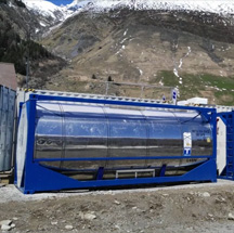
SBR technology, rough silt clearance, compact design


The wastewater plant must run fully automatically with a simple to operate, rugged control unit. The plant must react flexibly to foreign water inlets, the max. daily water volume is 180m3.
The aeration intensity is controlled via the oxygen content. Secondary sludge is pumped to sludge dewatering. The plant must be simple and quick to assemble, even by third party’s staff.
Used technology for wastewater cleaning
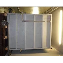
Wastewater plant, consisting of a rough pre-cleaning and several reactors which can be filled parallelly, working according to the SBR process.
Process flow of the sewage treatment plant (extract from the preliminary planning)
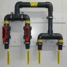
The water is pumped from the pump shaft provided by the customer into the machine house (container). Both pumps P1, P2 are operated alternately. The sensor SPS1 positioned in the pump shaft
3 possible switching/alerting states:
1.Alternating operation of one of the two pumps when level above dry run (ON/OFF)
2.Simultaneous operation of both pumps when maximum level reached (high load performance)
3.Alarm when alarm levels reached (both pumps above capacity level)
In the machine house, the water runs over the curved screen and then into the buffer shaft (BU) below. A sensor (SPF1) is installed in the buffer shaft, which monitors the water level constantly, as well as two submersed motor pumps (PF1, PF2). The control unit then differentiates between three different switching states through the integration of the water level over the course of time:
1. Normal cycle
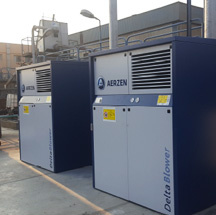
From a certain level in the buffer (BU), the alternating operation of both pumps (PF1, PF2) will start in order to maintain a normal cycle. Both bioreactors (R1 and R2) are always operated parallel and alternating. The normal cycle of the process flow starts with the filling of each bioreactor (R1 and R2). By switching on the blower – installed in the machine house – for the corresponding reactor (V1, V2), aeration will be started at the same time as filling.
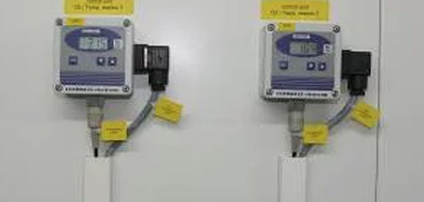
The further program flow is a sequence of aeration activation, aeration pauses and short aeration intervals to blend the sludge in the reactor (R1 and R2). During those phases, the concentration of the oxygen in the reactor is measured with a sensor installed in the reactor (SO1, SO2) and forwarded to the principal control room for checking. At the end of the normal cycle (standard duration = 6 to 8 hours), the sedimentation phase starts. All aggregates are switched off.
After one hour, the control unit determines the further program flow. When the level in the buffer (BU) has reached a sufficient height, the secondary sludge is removed after the sedimentation phase. The secondary sludge pump (PS1, PS2) of each reactor removes a defined amount of surplus sludge and forwards it into the sludge thickener (S1, S2) active at that time after it has gone through the sludge distribution. At the same time, clearwater is removed from the reactor, the control unit activates the corresponding clearwater pump (PK1, PK2) of the reactor for that purpose.
The water level in the reactor is monitored by the sensors (SB1, SB2). As soon as the lower water level, at which the removal process stops, is reached, the pump will switch off. A new cycle with filling will start.
2. Energy saving cycle (holiday mode)
If there is not enough water in the buffer during a normal cycle in order to guarantee a complete reactor filling, the device will switch into the energy saving mode. In this case, the clearwater will not be removed from the reactor.
The water will be ventilated with the blowers (V1, V2) in the reactors with reduced power while the water level in the buffer (BU) is constantly measured. After reaching the minimum water level, the control unit will switch directly into the normal cycle.
3. Overload (infiltration)
If both reactors run in normal operation and the water level in the buffer does not decrease to the normal level within a pre-defined time, the control unit will switch automatically into overload alarm.
Contact us for a free quotation
Do you have a question or need more information about a sewage treatment plant? We shall be happy to develop a suitable solution to your specific requirements.
Please call us on 01629 55839 or use the form below.
CONTACT US

Industrial Wastewater Treatment
Examples of applications that have the potential to generate waste water include, but are not limited to the following industries:
- Food processing
- Agricultural processes
- Breweries
- Wineries
- Mining
- Wash water from any activity and process effluent
Clearfox is a recognised market leader in the design, manufacture and supply of industrial wastewater treatment plants and industrial wastewater treatment process development. We provide intelligent solutions for industrial wastewater treatment:
- ensuring that they meet the stringent discharge compliances
- to recover and recycle water that can be reused in:
- cooling towers
- irrigation
- washing water
- process water
- to recover and recycle water from municipal sewage